Moduleur Build Guide
Build the Moduleur
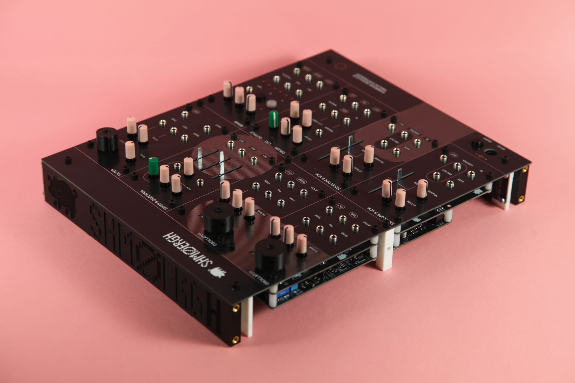
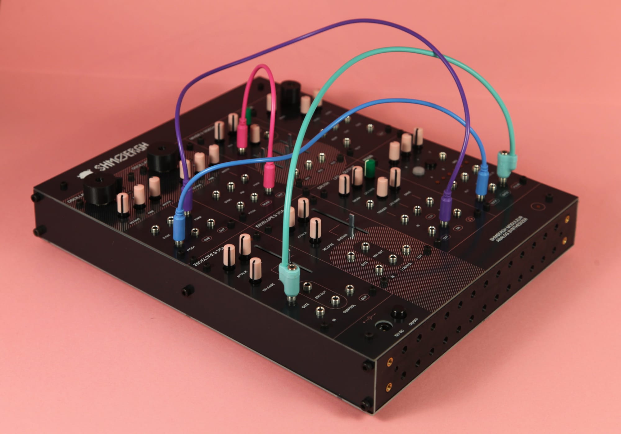
The Shmøergh Moduleur is a fully analog, standalone synthesizer system you can build yourself — enclosure included. When you’re done, you don’t get a loose collection of modules. You get a playable instrument.
All circuits, PCBs, firmware, and mechanical designs are open source / open hardware.
Why build it?
It's a real instrument
A complete standalone synth at the end of the process.
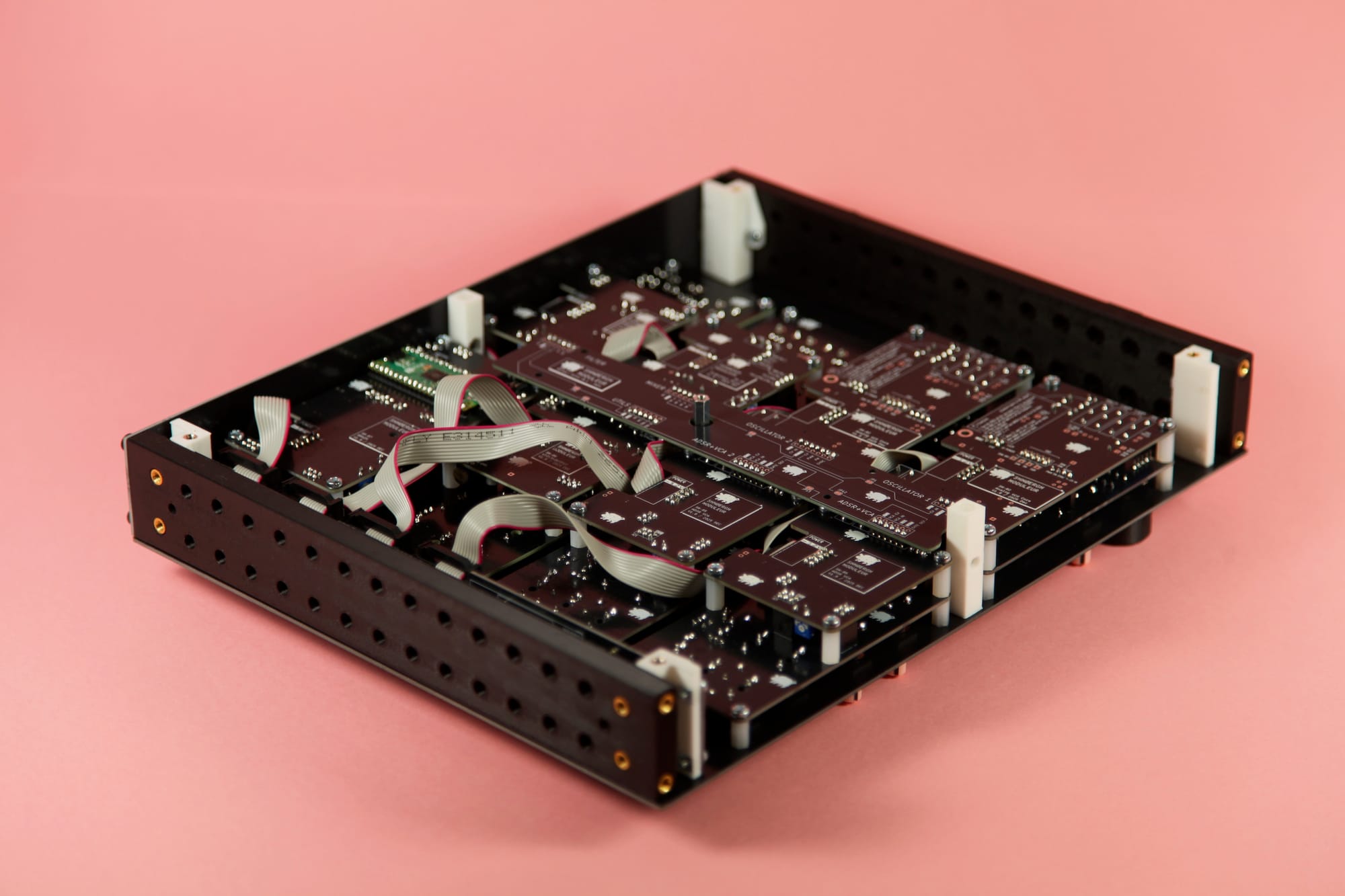
Full enclosure design included
Not just electronics — panels, structure, mechanical files.
Standalone + Eurorack compatible
Build the entire system or just a single module for your rack.
UI and core PCBs are separated
Redesign the control surface if you want. Keep the analog core.
Hackable digital Brain
RP2040 (Pico / Pico 2) based. Open firmware. Extend it.
Fun
Large boards. Clear signal flow. Solid mechanics.
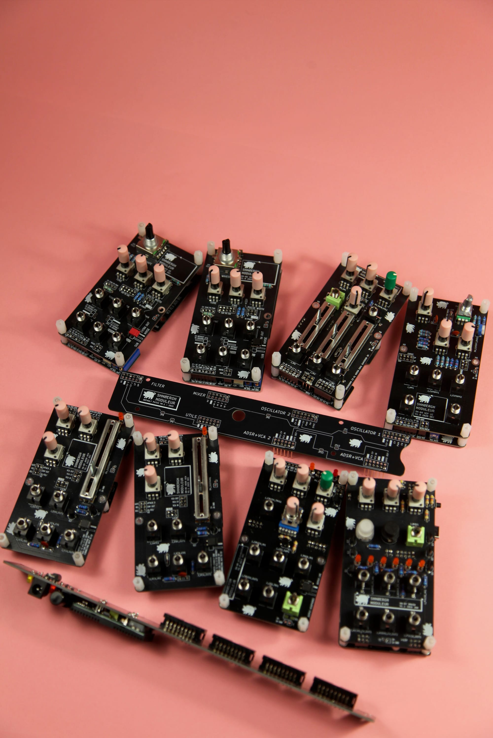
What’s inside
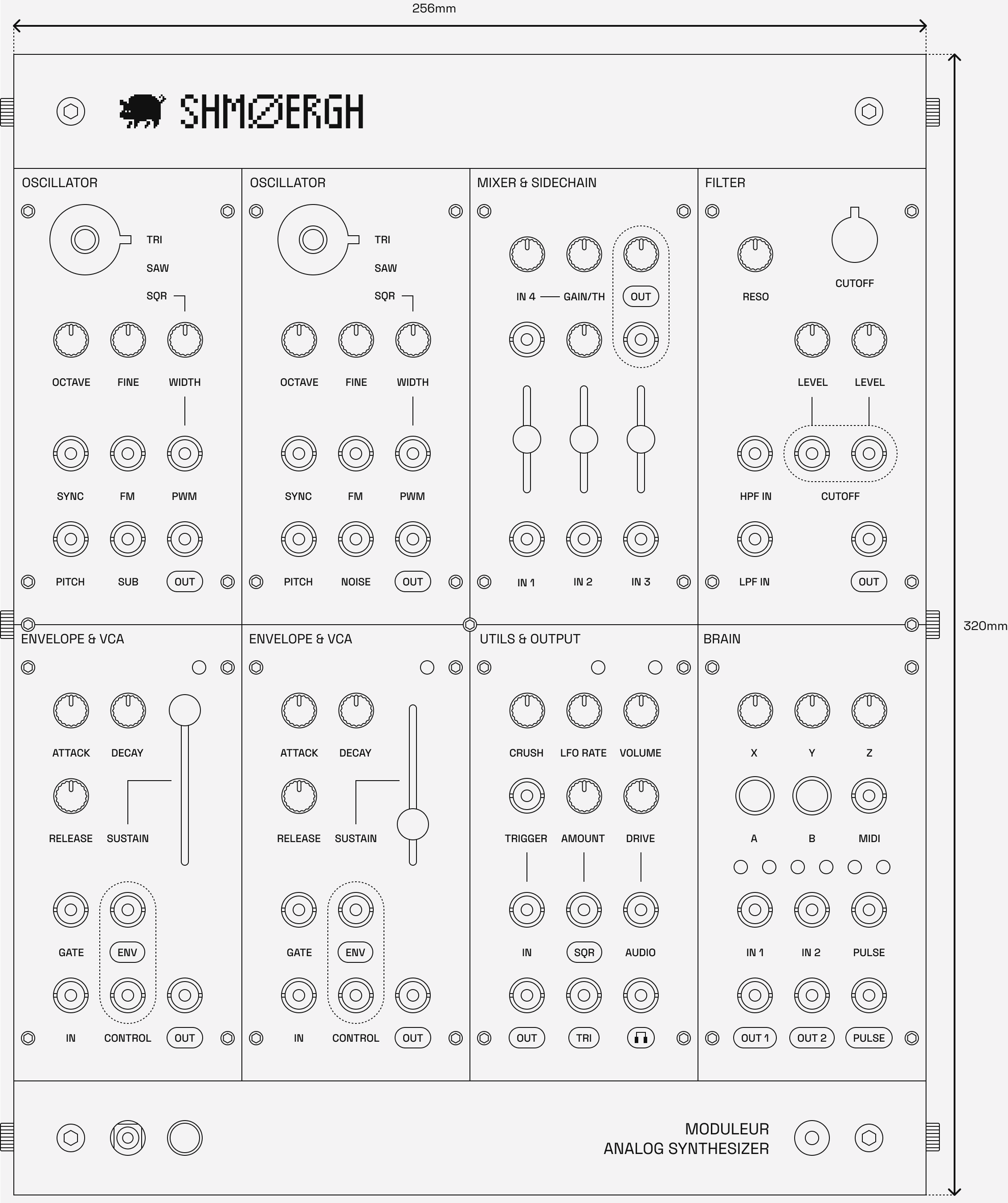
8 modules total
- VCO (x2): triangle, saw, square, sub, noise
- Mixer with sidechain compressor
- Diode ladder filter
- ADSR + VCA (x2)
- Utils: analog bit crusher, LFO, output interface with overdrive + headphones
- Brain: universal digital module based on Raspberry Pi Pico / Pico 2
The system follows standard Eurorack conventions
- ±12 V rails
- 10-pin power
- Reverse polarity protection
- 1 V/oct VCO tracking
Design priorities: robustness, component availability, clear signal flow.
Not a beginner project
You should be comfortable with:
- Reading schematics
- Ordering PCBs and sourcing BOMs
- Debugging analog circuits
- Working safely with ±12V systems
If this is your first build, start smaller.
The Files
All design files are available in the Moduleur GitHub repository:
- Schematics
- KiCad projects
- Gerbers
- BOMs
- Panel files
- Firmware
- Simulation files and test notes
Development is ongoing. Revisions may change between versions.
Build questions?
We have a Discord server where builders discuss debugging, substitutions, firmware tweaks, and custom panels.
If you’re building a Moduleur, you should be part of it.